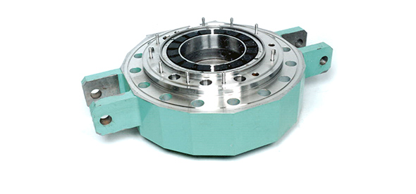
UK ABWR Reactor Internal Pump (RIP)
Each Reactor Internal Pump (RIP) is directly mounted to the bottom of the RPV and supplies coolant (water) to the reactor core. The station’s power output can be controlled by changing the RIP’s rotation speed. This design takes away the need for external circulation pipes and as such gives an even greater reduction in potential radiation exposure for workers. This exposure is well within UK limits – and far lower than day-to-day exposure to natural background radiation. This is a major design difference between the UK ABWR and previous designs of BWR.
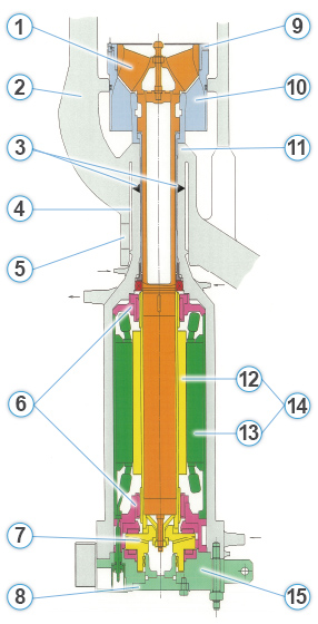
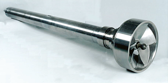
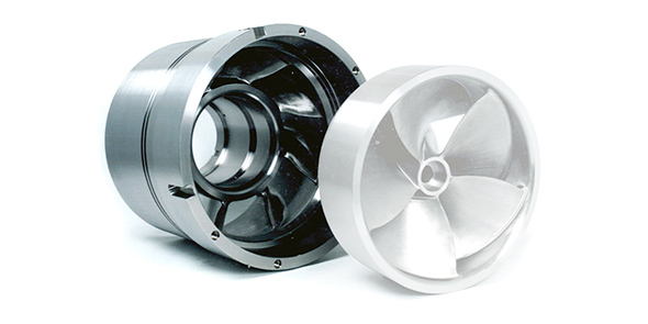
- Impeller and Shaft
1. Impeller and Shaft
- Reactor Pressure Vessel
2. Reactor Pressure Vessel
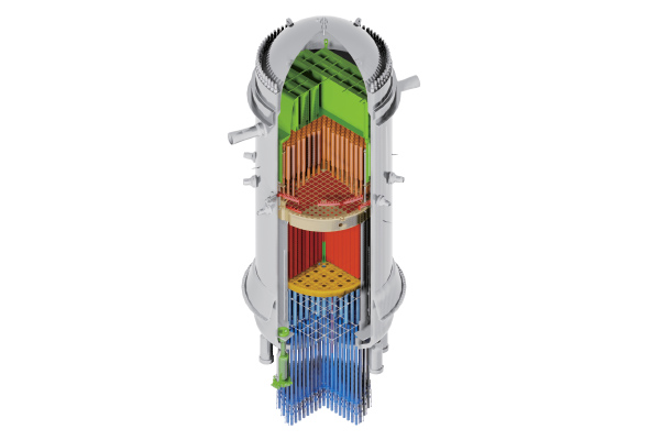
• For more information go to the Reactor Pressure Vessel page. - Welding
- Nozzle Gap
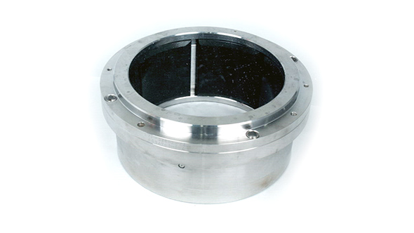
- Inspection Window
- Tilting Pad Radial Bearing
6. Tilting Pad Radial Bearing
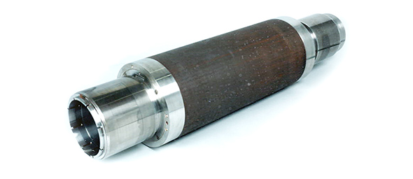
- Thrust Disk
7. & 8. Thrust Disk & Auxiliary Cover
- Auxiliary Cover
- Wearing
- Diffuser
10. Diffuser
- Nozzle
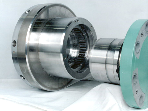
- Rotor
12. Rotor
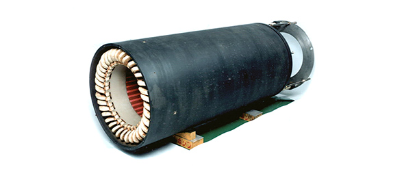
- Stator
13. Stator
- Wet Motor
- Motor Cover
15. Motor Cover